

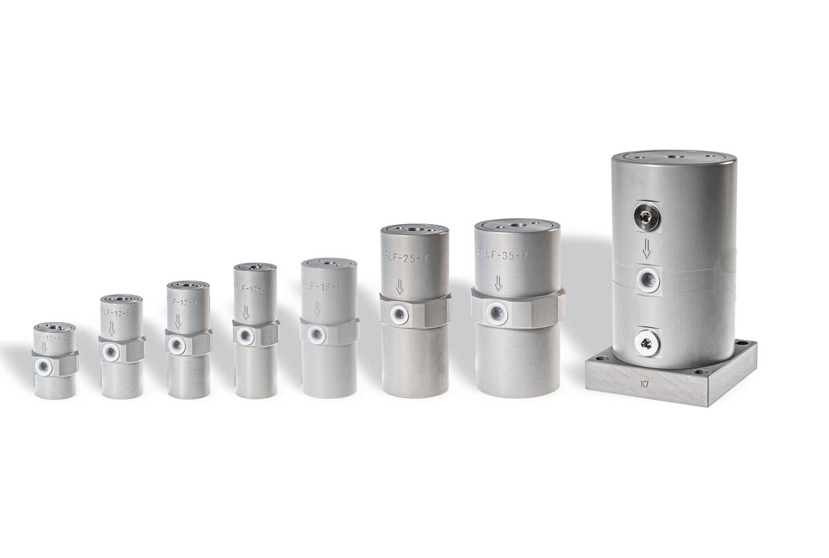
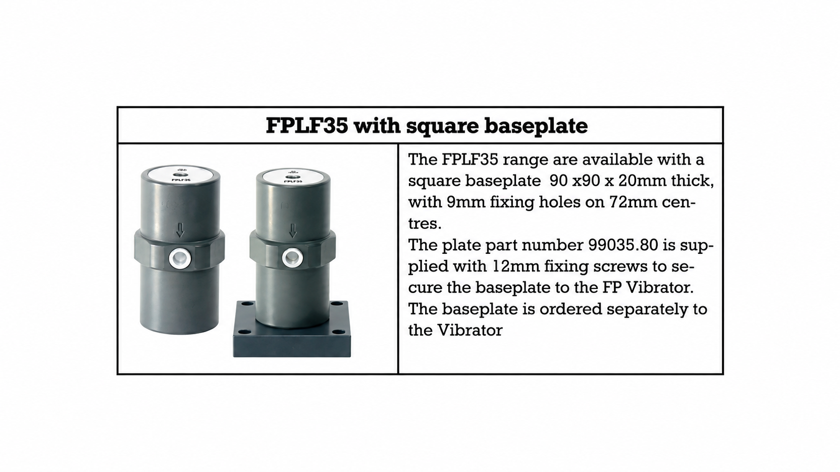
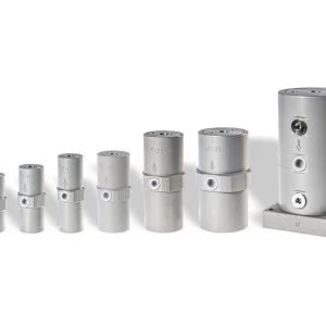
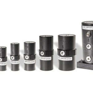
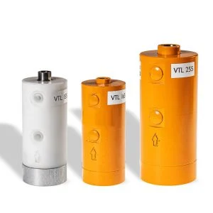
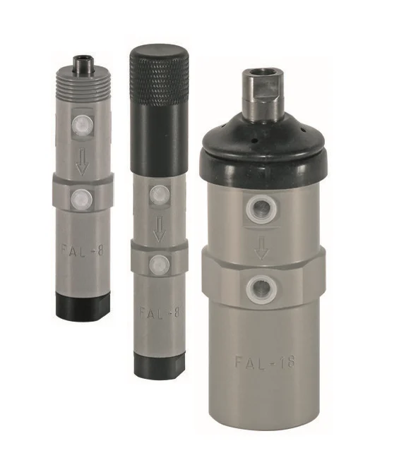
FPLF Series Lubrication-Free Pneumatic Piston Vibrator
Price range: $279.00 through $1,707.00
Installation and Operating Instructions for
pneumatic piston vibrators Series «FPLF»
Installations– und Betriebsvorschriften für
pneumatische Kolbenvibratoren Serie «FPLF»
Instructions d’installation et d’utilisation des
vibrateurs pneumatiques à piston séries «FPLF»


The pneumatic vibrators (FPLF) comply with EC Machinery Directive
2006/42/EC.
The Standards DIN EN ISO 12100:2010 must be observed in particular.
Die pneumatischen Vibratoren (FPLF) entsprechen der EG-Maschinenrichtlinien
2006/42/EG. Insbesondere sind die Normen DIN EN ISO 12100:2010 beachtet.
Les vibrateurs pneumatiques (FPLF) sont conformes aux directives européennes
sur les machines 2006/42 CE et en particulier aux normes DIN EN ISO 12100:2010.
Managing Director
1. Feb. 2014

power lines, the compressed air supply is turned off.
Vibrator und Zuleitungen die Druckluft sicher abgestellt ist.
ou d’autres travaux sur le vibrateur ou les conduites d’alimentation.

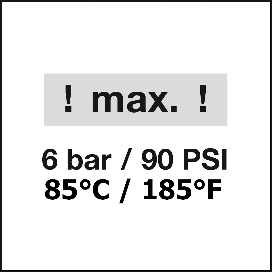
The maximum working pressure may not exceed
6 bar (90 PSI).
Der maximale Arbeitsdruck darf
6 bar (90 PSI) nie übersteigen!
La pression de travail maximum ne doit pas dépasser
6 bar (90 PSI).
1.
The ambient temperature during operation may not exceed
85°C (185°F).
Die Umgebungstemperatur soll während des Betriebes
85°C (185°F) nie übersteigen.
La température ambiante ne doit pas dépasser
85°C (185°F).
2.
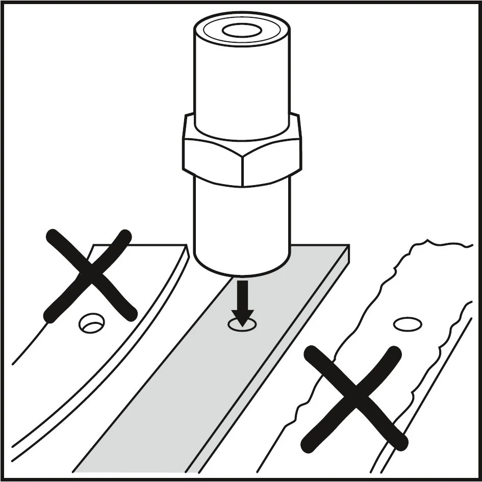
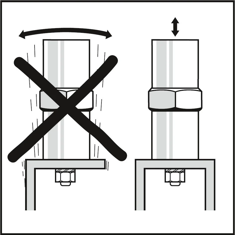
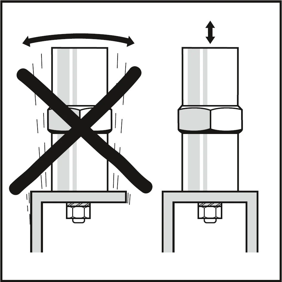
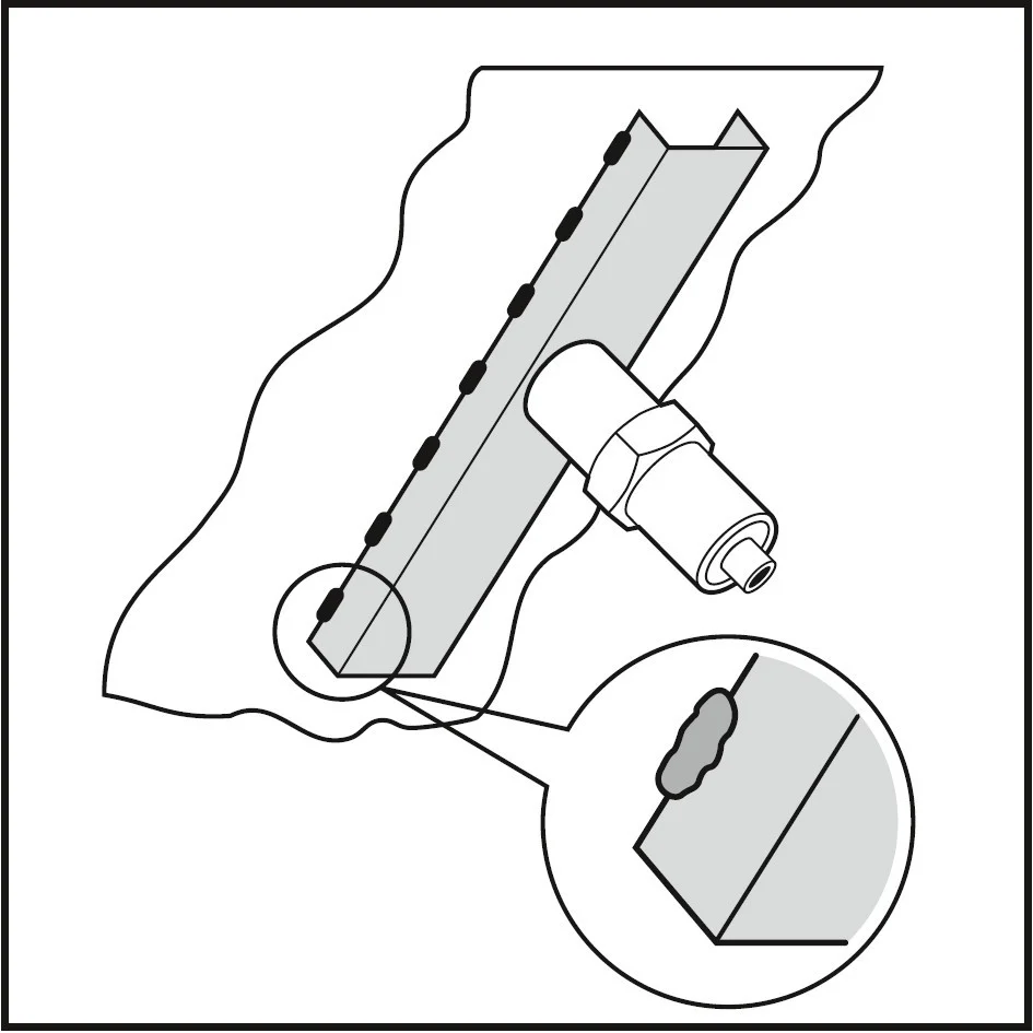
The clamping surface must be clean and flat. It is advisable to use a
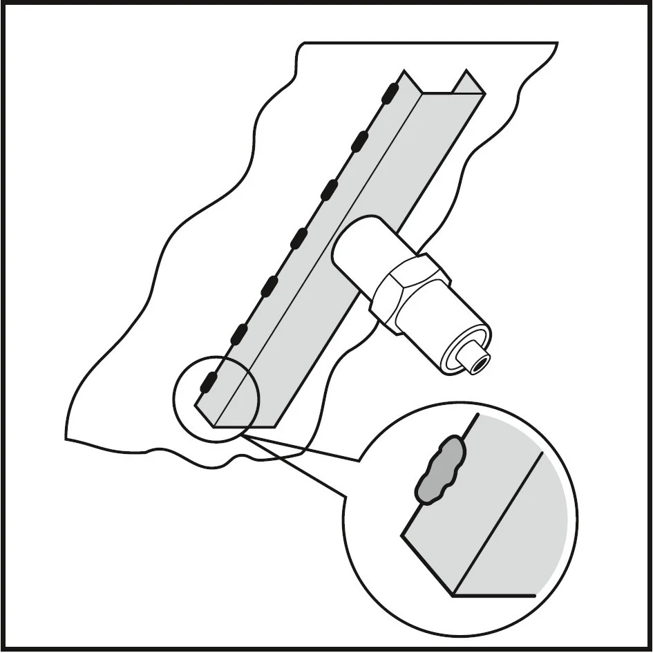
stiffening rod (U-section iron bar) as the substructure and that it be welded
to the object, thus transferring the vibration energy in an optimum manner.
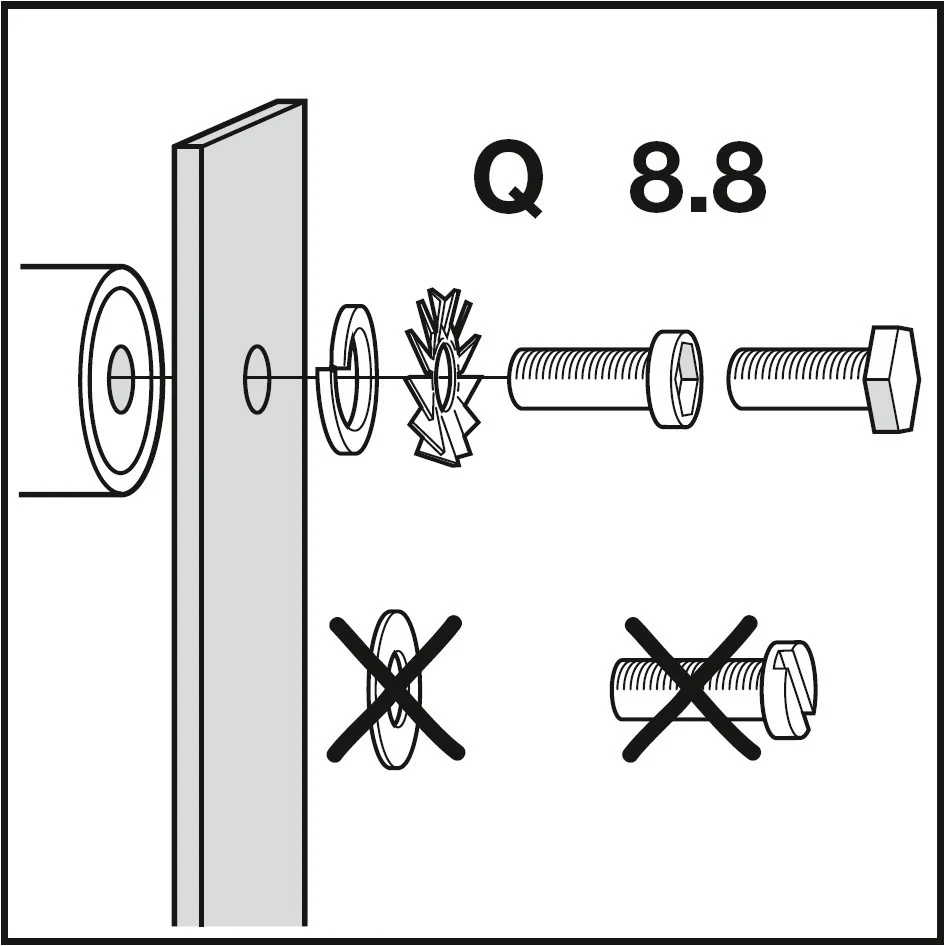
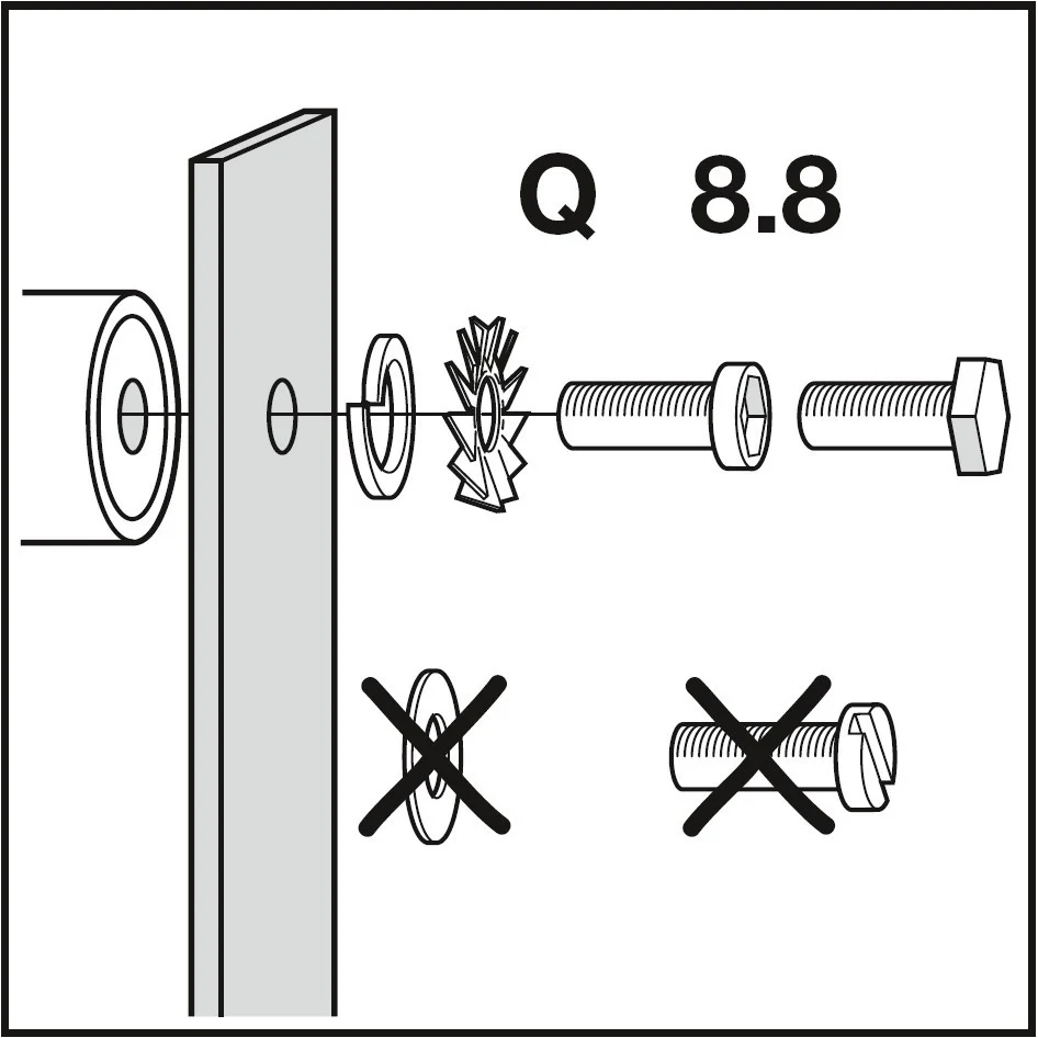
Allen screws of 8.8 quality are to be used for attachment.
(not slotted screws!) Tightening torques and effective thread lengths
are to be used across the following range:
Die Aufspannfläche muss sauber und plan sein. Es wird empfohlen, ein
Versteifungsprofil (U-Eisen) als Unterbau zu verwenden, welches an das Objekt
geschweisst wird und so die Vibrationsenergie optimal verteilen kann.
Zur Befestigung sind Inbus-Schrauben der Qualität 8.8 zu verwenden.
(Keine Schlitzschrauben!) Die Anzugsdrehmomente und Gewindenutzlängen
sollen in folgendem Bereich liegen:
La surface d’ablocage doit être propre et plane. Il est conseillé d’utiliser
un profilé de renforcement (fer en U) comme substructure. Souder ce fer à
l’appareil de manière à ce qu’il puisse répartir de façon optimale l’énergie
vibratoire. Pour la fixation, utiliser des vis à six pans creux de qualité 8.8.
(pas de vis à fente!) Les couples de serrage et les longueurs utiles du
filetage doivent être compris dans les plages suivantes:
| models Modelle modèles | thread Gewinde filetage | torque, Drehmoment, couple | effective thread length, Gewindenutzlänge, longueur utile de filetage | ||
|---|---|---|---|---|---|
| min. | max. | min. | max. | ||
| FPLF-12 | M8 | 15 Nm | 21 Nm | 8 mm | 12 mm |
| FPLF-18 | M10 | 30 Nm | 42 Nm | 10 mm | 14 mm |
| FPLF-25 | M12 | 50 Nm | 72 Nm | 12 mm | 17 mm |
| FPLF-35 | M12 | 50 Nm | 72 Nm | 12 mm | 17 mm |
| FPLF-50 | M16 / 4xM8 | 125 / 15 Nm | 175 / 21 Nm | 14 mm | 17 mm |
| FPLF-60 | M16 / 4xM8 | 125 / 15 Nm | 175 / 21 Nm | 14 mm | 17 mm |
| FPLF-95 | 4xM12 | 50 Nm | 72 Nm | ||

NOTE:
The fastening screw thread is to be found in the smaller Ø frontal piece!
The thread in the other end cap (air exhaust port) is not metric!
HINWEIS:
Das Befestigungsgewinde befindet sich im Stirnstück mit kleinerem Ø!
Das Gewinde auf der gegenüberliegenden Seite (Luftauslass) ist nicht metrisch!
REMARQUE:
Le filetage de fixation se trouve dans la pièce frontale avec un Ø plus petit!
Le filetage dans l‘autre bouchon (prise d‘échappement) n‘est pas métrique!
DANGER:
Loose screws can cause the vibrator to fall down and cause injuries!
GEFAHR:
Gelöste Verschraubungen können das herunterfallen des Vibrators
und als Folge Personenschäden bewirken!
DANGER:
Des raccords desserrés peuvent faire tomber le vibrateur et
blesser des personnes!
3.
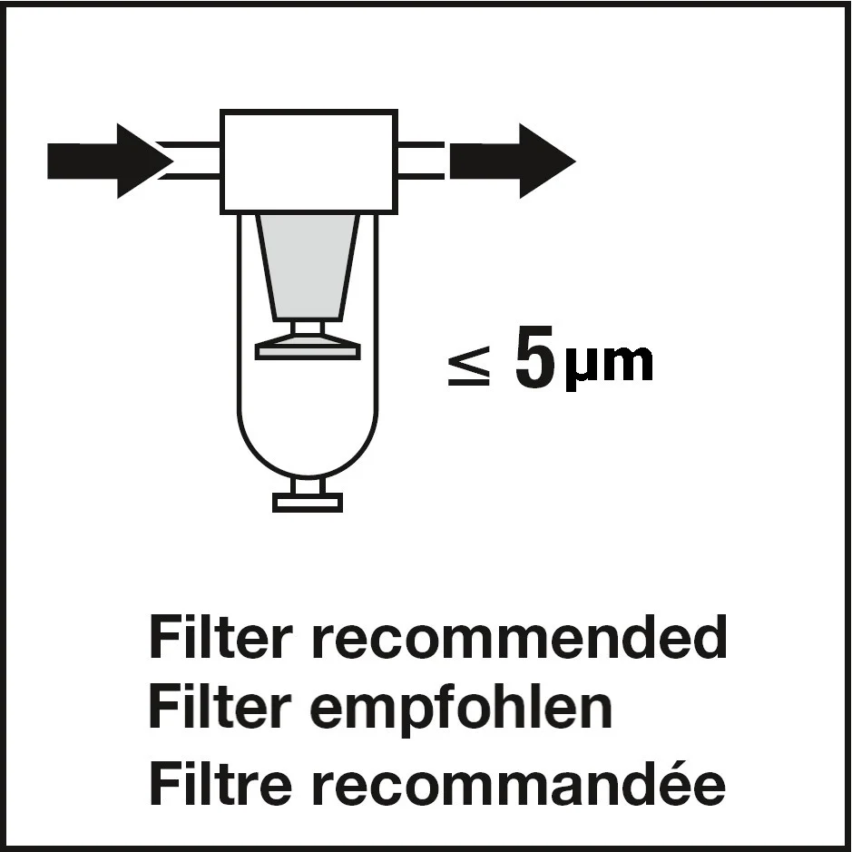
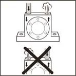
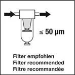
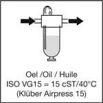
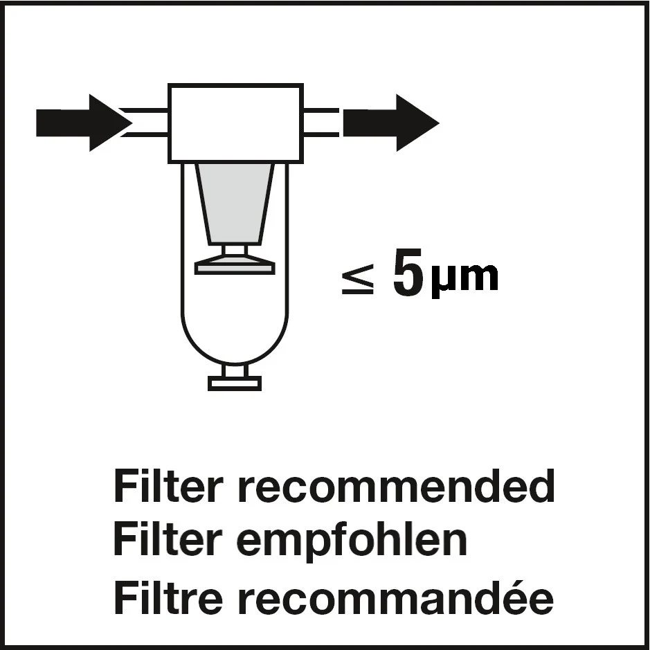
The air pressure supply must be
clean (Filter < 5 um)
Die Druckluft muss
sauber sein (Filter < 5 um).
L’air comprimé doit être
propre (filtre < 5 um)
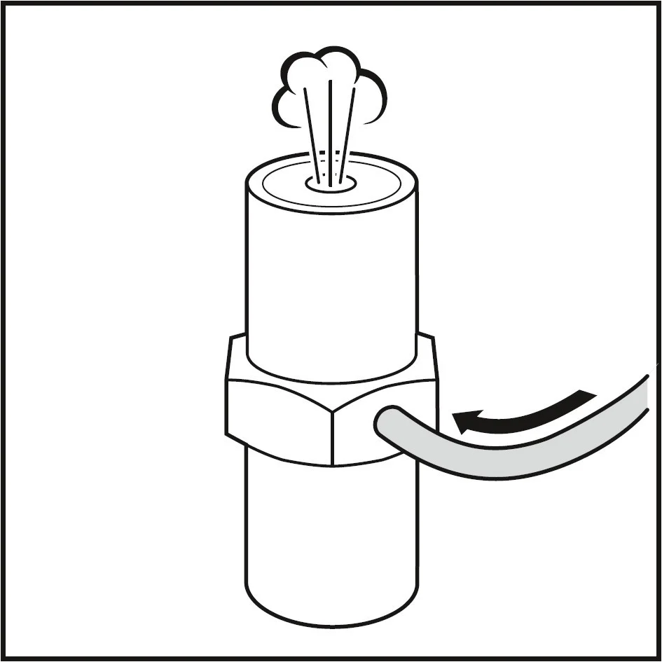
DANGER:
Loosened compressed air hoses can cause personal injury
(to eyes)!
GEFAHR:
Gelöste Druckluft-Schläuche können Personen verletzen
(Augen)!
DANGER:
Des tuyaux d’air comprimé desserrés peuvent blesser des
personnes (yeux)!
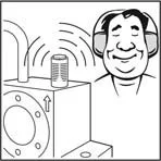
DANGER:
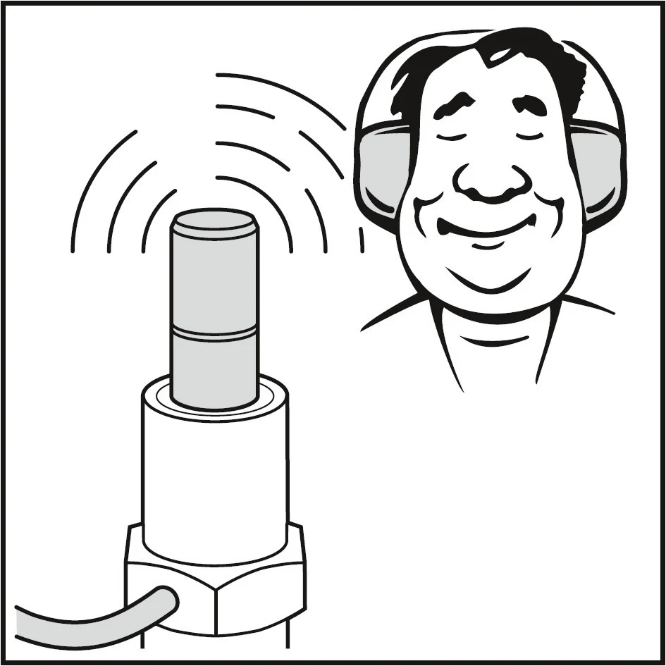
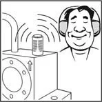
No operation without silencer
(extreme dB levels/ear injuries)!
GEFAHR:
Der Betrieb ohne Schalldämpfer sollte vermieden werden
(ggf Ohrenschäden)!
DANGER:
Ne jamais mettre en marche sans silencieux
(danger pour les oreilles)!
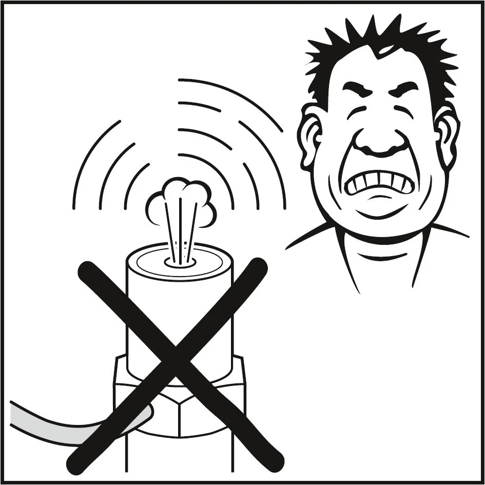
DANGER:
The exhaust is under pressure and this may cause injuries
(eye injuries)!
GEFAHR:
Der Luftauslass steht unter Druck und dies kann zu Verletzungen
führen (Augen)!
DANGER:
Le tube d’échappement sous pression peut blesser des personnes
(danger pour les yeux)!
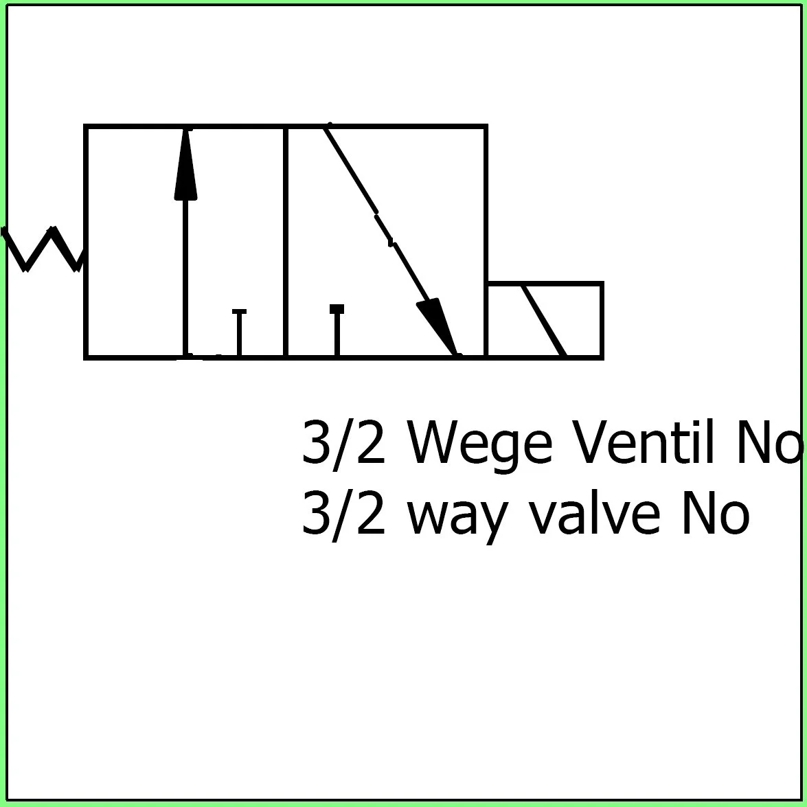
4. NOTE:
If the device is operated with very short stop intervals
(< 3 secs.), then a control valve needs to be employed that
will permit the venting of the vibrator to the atmosphere,
so that the piston can take up its start position.
HINWEIS:
Erfolgt der Betrieb mit sehr kurzen Stop-Intervallen
(< 3 Sek.), so ist ein Steuerventil einzusetzen, welches
die Entlüftung des Vibrators in die Atmosphäre erlaubt,
damit der Kolben sofort seine Start-Position einnehmen kann.
IMPORTANT:
En cas de fonctionnement avec des intervalles d’arrêt très courts
(< 3 sec.), monter une vanne pilote permettant la purge du
vibrateur dans l’atmosphère afin que le piston puisse
immediatement se mettre en position Start.
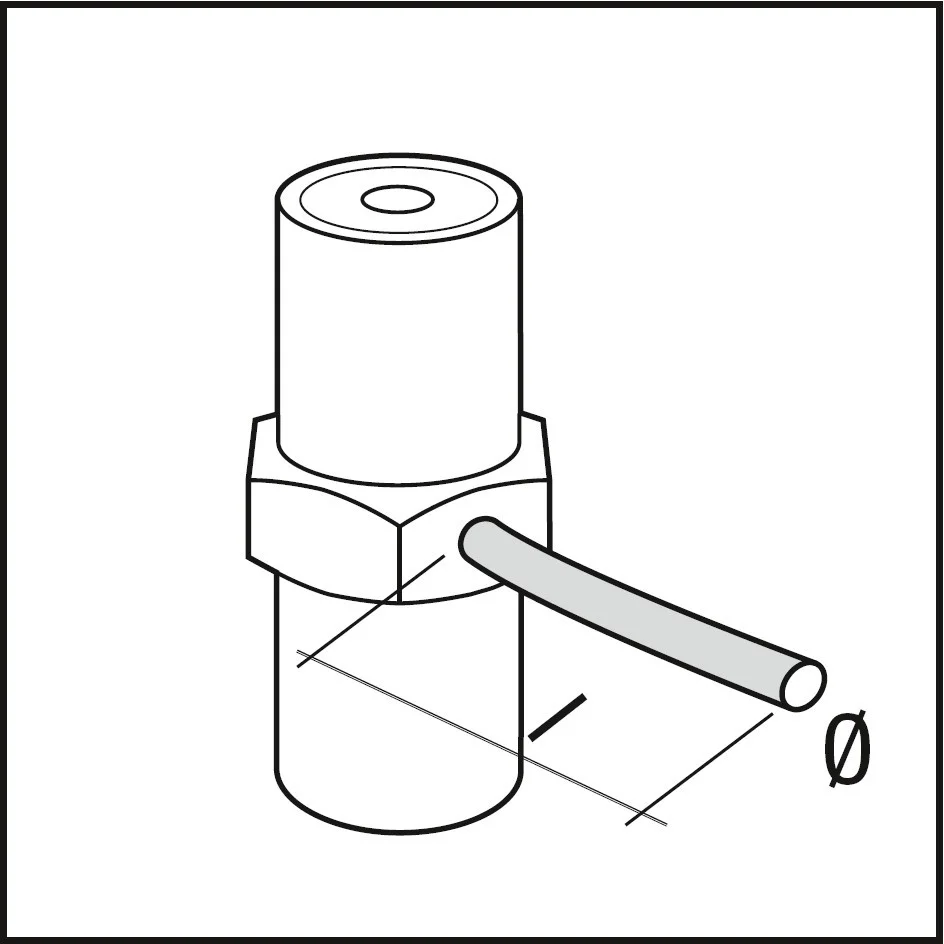
| Piston vibrators Kolbenvibrator Piston vibrateur | inside Ø innen Ø intérieur Ø | Length I Länge I Longeur I |
|---|---|---|
| FPLF-12 / -18 / -25 | 4 mm | < 2 m |
| FPLF-35 / -50 / -60 | 6 mm | < 3 m |
| FPLF-95 | 10 mm | < 5 m |
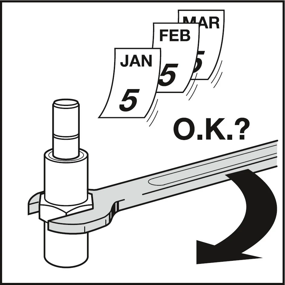
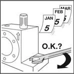
5. IMPORTANT:
After the initial run and at least once a month, check the
correct mounting of the vibrator, the air connection and the
silencer.
WICHTIG:
Überprüfen Sie nach dem ersten Betriebslauf sowie mindestens
einmal monatlich die korrekte Befestigung des Vibrators,
Luftanschluss und Schalldämpfer.
IMPORTANT:
Vérifiez après un premier fonctionnement et au moins mensuellement
la fixation correcte du vibrateur, du raccord pneumatique et du
silencieux.
6.
If you notice a loss of power on the part of the vibrator or if it even
stops, then remove the air connector and the silencer. Dismantle the
vibrator and clean its parts with petrol. Then sparingly grease the piston
and its bore, using the following grease
(Klüber synth UH1 14-31), and reassemble the parts.
(First fit the base to the casing). Check the silencer as well for
contamination. If necessary, wash it out with paraffin or replace it.
Wird ein Leistungsabfall oder sogar ein stoppen des Vibrators festgestellt,
so entfernen Sie den Luftanschluss und den Schalldämpfer. Demontieren Sie
den Vibrator und reinigen Sie die Teile mit Petrol. Fetten Sie anschliessend
den Kolben und die Bohrung sparsam ein und montieren Sie die Teile wieder
zusammen (Klüber synth UH1 14-31).
(Zuerst den Sockel in das Gehäuse montieren) Überprüfen Sie auch den
Schalldämpfer auf Verschmutzung. Waschen Sie ihn ggf. mit Petrol aus oder
ersetzen Sie ihn.
Si vous constatez une diminution de la puissance, voire l’arrêt du
vibrateur, enlevez le raccord pneumatique et le silencieux. Démontez le
vibrateur et nettoyez les pièces au pétrole. Graissez ensuite légèrement
le piston et le percage avec la graisse suivant
(Klüber synth UH1 14-31) et assemblez de nouveau les
pièces (monter tout d‘abord le socle dans le boîtier). Vérifier aussi si
le silencieux est propre. Si nécessaire lavez-le au pétrole ou remplacez-le.
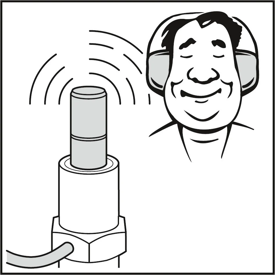
WARNING:
Wear ear protection during above procedure!
WARNUNG:
Tragen Sie während der obigen Arbeiten einen Gehörschutz!
AVERTISSEMENT:
Portez des boules-quies pendant ce processus!
NOTE:
Dirt will lead to the failure of the vibrator!
HINWEIS:
Schmutz führt zum Ausfall des Vibrators!
REMARQUE:
Les saletés provoquent la défaillance du vibrateur!
7.
After approx. 1,500 hours of operation, it is advisable
to lubricate the vibrator sparingly in its dismantled state and after
cleaning, using the following grease
(Klüber synth UH1 14-31).
See item 6.
Nach ~1‘500 Betriebsstunden ist es empfehlenswert, den Vibrator im
zerlegten Zustand nach erfolgter Reinigung sparsam nachzufetten
(Klüber synth UH1 14-31).
Siehe Punkt 6.
Après ~1‘500 heures de service il est recommandé d’ajouter un peu de
graisse au vibrateur démonté et nettoyé. Pouvez utiliser la graisse
suivant (Klüber synth UH1 14-31).
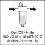
Voir point 6.
NOTE:
Greases of different viscosity will reduce the operating frequency or
can lead to the piston seizing as a result of the grease becoming resinous.
HINWEIS:
Fette mit anderer Viskosität reduzieren die Betriebsfrequenz oder
können zum Blockieren des Kolbens infolge Verharzens des Fettes führen.
REMARQUE:
Les graisses de viscosité différente diminuent la fréquence de
fonctionnement ou peuvent provoquer le blocage du piston du fait de
la résinification de la graisse.
8. Possible faults:
(• after installation / – during operation)
Fehlermöglichkeiten:
(• nach Neumontage / – während Betrieb)
Erreurs possibles:
(• après l’installation / – durant utilisation)
9. Repairs / spare parts:
Repairs may only be performed by trained personnel.
Spare parts can be ordered based on the model number.
Reparaturen / Ersatzteile:
Reparaturen dürfen nur durch geschultes Personal ausgeführt werden.
Ersatzteile können auf Grund der Modellnummer bestellt werden.
Réparations / pièces de rechange:
Les réparations doivent être effectuées par des personnels qualifiés.
Les pièces de rechange peuvent être commandées sur la base du numméro
de modèle.
10.
The parts of used vibrators can be recycled:
piston → steel
spring → steel
zugeführt werden:
Kolben → Stahl
Feder → Federstahl
Toutes les pièces des vibrateurs usagés sont aptes au recyclage:
piston → acier
ressort → acier
NOTE:
For technical details / information:
www.findeva.com
HINWEIS:
Für technische Daten / Informationen:
www.findeva.com
INDICATION:
Données / informations techniques:
www.findeva.com


Service for lubrication free linear-vibrators /
Wartung ölfreie Linear-Vibratoren
Removing the air connection and silencer.
Entfernen von Luftanschluss und Schalldämpfer.
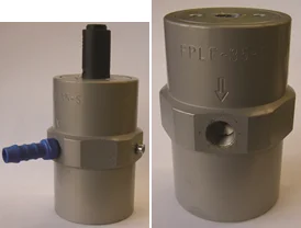
Disassemble with pin wrench
(right-hand thread).
Demontieren mit Stiftschlüssel
(Rechtsgewinde).
First remove the cap (air outlet), then the piston and
spring. Then loosen the socket.
Zuerst den Deckel (Luftauslass), dann Kolben und Feder
entnehmen. Erst dann den Sockel lösen.
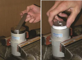
Remove Teflon tape residues from the cap.
Teflonband-Reste vom Deckel entfernen.
Cleaning of all parts with petrol or benzine.
Reinigen von allen Teilen mit Petrol oder Reinigungsbenzin.
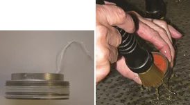
Dry everything well. Make sure that the parts are free of
lint and dust.
Alles gut trocknen. Darauf achten, dass die Teile fussel-
und staubfrei sind.
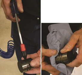
Using a very small amount of
Klüber synth UH1 14-31,
grease the housing (inside), the piston and the spring.
Mit sehr wenig
Klüber synth UH1 14-31
das Gehäuse (innen), den Kolben und die Feder einfetten.
Apply the grease lightly to the housing interior,
piston and spring as shown.
First mount the socket in the housing.
Zuerst den Sockel in das Gehäuse montieren.
Insert the spring and make sure that it rests neatly on the base.
Then insert the piston without applying much pressure.
Die Feder einlegen und darauf achten, dass diese sauber auf
dem Sockel aufliegt. Dann den Kolben ohne grossen Druck
einführen.
Tighten with pin wrench.
Mit dem Stiftschlüssel anziehen.
Check the silencer for dirt. If necessary, clean with petrol or
replace.
Den Schalldämpfer auf Verschmutzung kontrollieren.
Gegebenenfalls mit Petrol einigen oder ersetzen.
Test with max. 6bar pressure.
Test mit max. 6bar Druck.


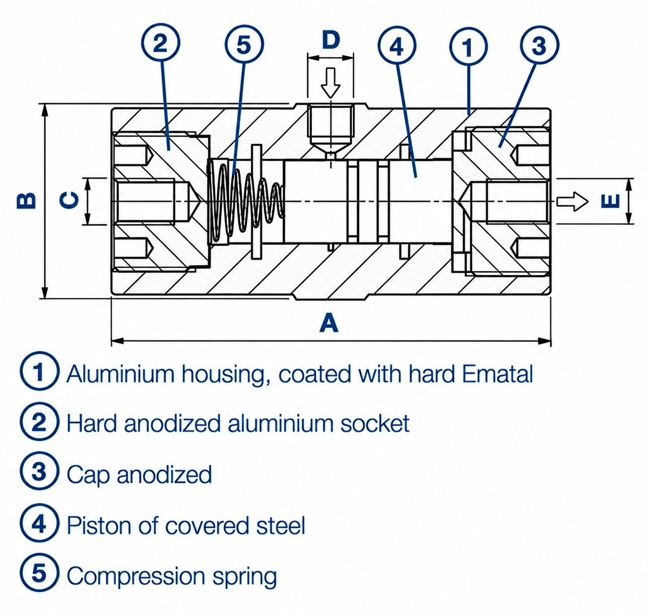
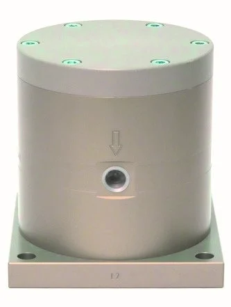
Piston-Vibrators FPLF-12 to 35
Lubrication-free
pneumatic vibrators for linear vibration with unlimited fine-tuning
facilities for amplitude and frequency. Wide range.
Properties
- Quiet and efficient
- Lubrication-free
- Rated frequency 2’400 – 9’300 min-1
- Force 32 – 6’066 N
- Continuously variable
- Applicable up to 120°C, HT version up to 150°C and LT version
down to -40°C on request - Resistant against extreme environmental conditions
- Also available with ATEX certification
Field of application
- For foodstuffs and pharmaceuticals
- Driving conveyor and discharge chutes
- Loosening or compacting of bulk solids
- Activating of mechanical processes
- Filling facilities
Construction
Extra hard and corrosion-resistant surface through aluminium oxide,
generated by titaniferous electrolyte.
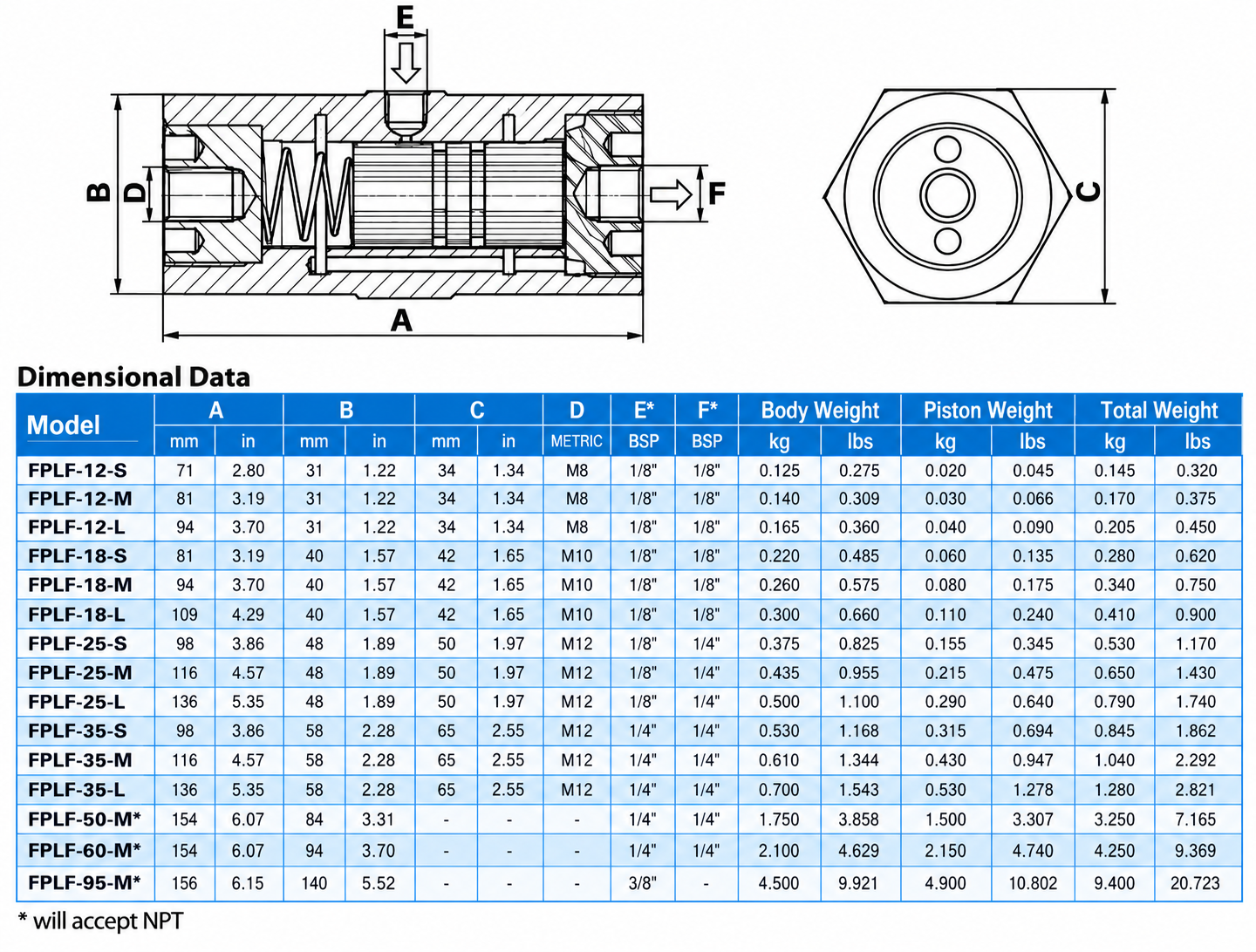
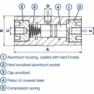
Dimensions and weights
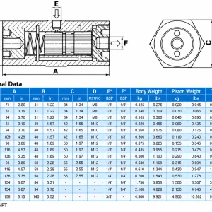
| Model | A [mm] | B (ws) [mm] | C | D Thread | E Thread | Weight [kg] |
|---|---|---|---|---|---|---|
| FPLF-12-XS | 50 | 34 | M8 | G 1/8” | G 1/8” | 0.10 |
| FPLF-12-S | 71 | 34 | M8 | G 1/8” | G 1/8” | 0.15 |
| FPLF-12-M | 81 | 34 | M8 | G 1/8” | G 1/8” | 0.18 |
| FPLF-12-L | 94 | 34 | M8 | G 1/8” | G 1/8” | 0.21 |
| FPLF-18-S | 81 | 42 | M10 | G 1/8” | G 1/8” | 0.30 |
| FPLF-18-M | 94 | 42 | M10 | G 1/8” | G 1/8” | 0.35 |
| FPLF-18-L | 109 | 42 | M10 | G 1/8” | G 1/8” | 0.42 |
| FPLF-25-S | 98 | 50 | M12 | G 1/8” | G 1/4” | 0.55 |
| FPLF-25-M | 116 | 50 | M12 | G 1/8” | G 1/4” | 0.67 |
| FPLF-25-L | 136 | 50 | M12 | G 1/8” | G 1/4” | 0.82 |
| FPLF-35-S | 98 | 65 | M12 | G 1/4” | G 1/4” | 0.93 |
| FPLF-35-M | 116 | 65 | M12 | G 1/4” | G 1/4” | 1.13 |
| FPLF-35-L | 136 | 65 | M12 | G 1/4” | G 1/4” | 1.38 |
Aluminium housing, coated with hard Ematal
Hard anodized aluminium socket
Cap anodized
Piston of covered steel
Compression spring
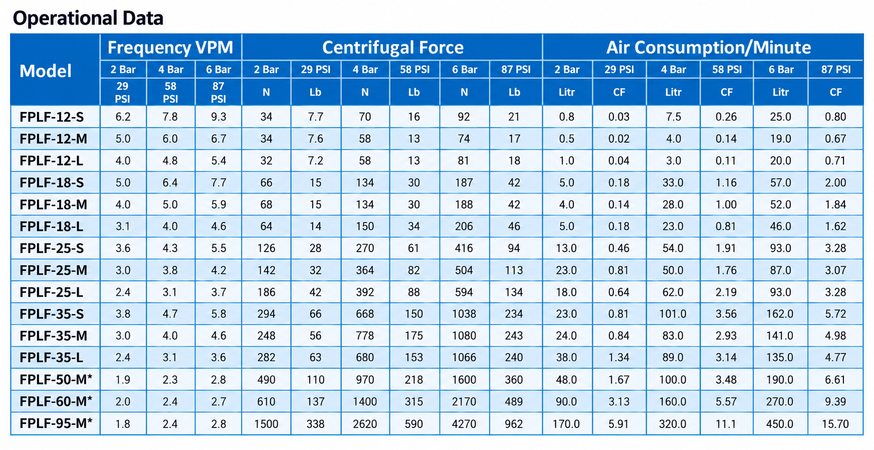
Technical data
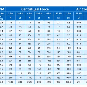
| Model | Vibrations [x 1000 min-1] | Force [N] | Air consumption [l/min] | ||||||
|---|---|---|---|---|---|---|---|---|---|
| 2 bar | 4 bar | 6 bar | 2 bar | 4 bar | 6 bar | 2 bar | 4 bar | 6 bar | |
| FPLF-12-XS | 6.0 | 9.0 | 11.5 | 22 | 48 | 68 | 0.8 | 6.0 | 15.0 |
| FPLF-12-S | 6.2 | 7.8 | 9.3 | 34 | 70 | 92 | 0.8 | 7.5 | 25.0 |
| FPLF-12-M | 5.0 | 6.0 | 6.7 | 34 | 58 | 74 | 0.5 | 4.0 | 19.0 |
| FPLF-12-L | 4.0 | 4.8 | 5.4 | 32 | 58 | 81 | 1.0 | 3.0 | 20.0 |
| FPLF-18-S | 5.0 | 6.4 | 7.7 | 66 | 134 | 187 | 5.0 | 33.0 | 57.0 |
| FPLF-18-M | 4.0 | 5.0 | 5.9 | 68 | 134 | 188 | 4.0 | 28.0 | 52.0 |
| FPLF-18-L | 3.1 | 4.0 | 4.6 | 64 | 150 | 206 | 5.0 | 23.0 | 46.0 |
| FPLF-25-S | 3.6 | 4.3 | 5.5 | 126 | 270 | 416 | 13.0 | 54.0 | 93.0 |
| FPLF-25-M | 3.0 | 3.8 | 4.2 | 142 | 364 | 504 | 23.0 | 50.0 | 87.0 |
| FPLF-25-L | 2.4 | 3.1 | 3.7 | 186 | 392 | 594 | 18.0 | 62.0 | 93.0 |
| FPLF-35-S | 3.8 | 4.7 | 5.8 | 294 | 668 | 1’038 | 23.0 | 101.0 | 162.0 |
| FPLF-35-M | 3.0 | 4.0 | 4.6 | 248 | 778 | 1’080 | 24.0 | 83.0 | 141.0 |
| FPLF-35-L | 2.4 | 3.1 | 3.6 | 282 | 680 | 1’066 | 38.0 | 89.0 | 135.0 |


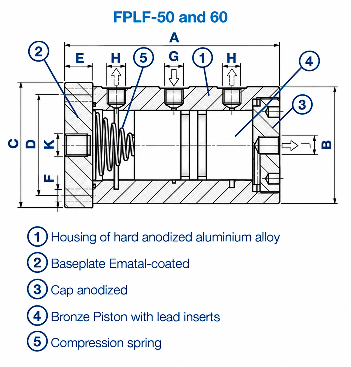
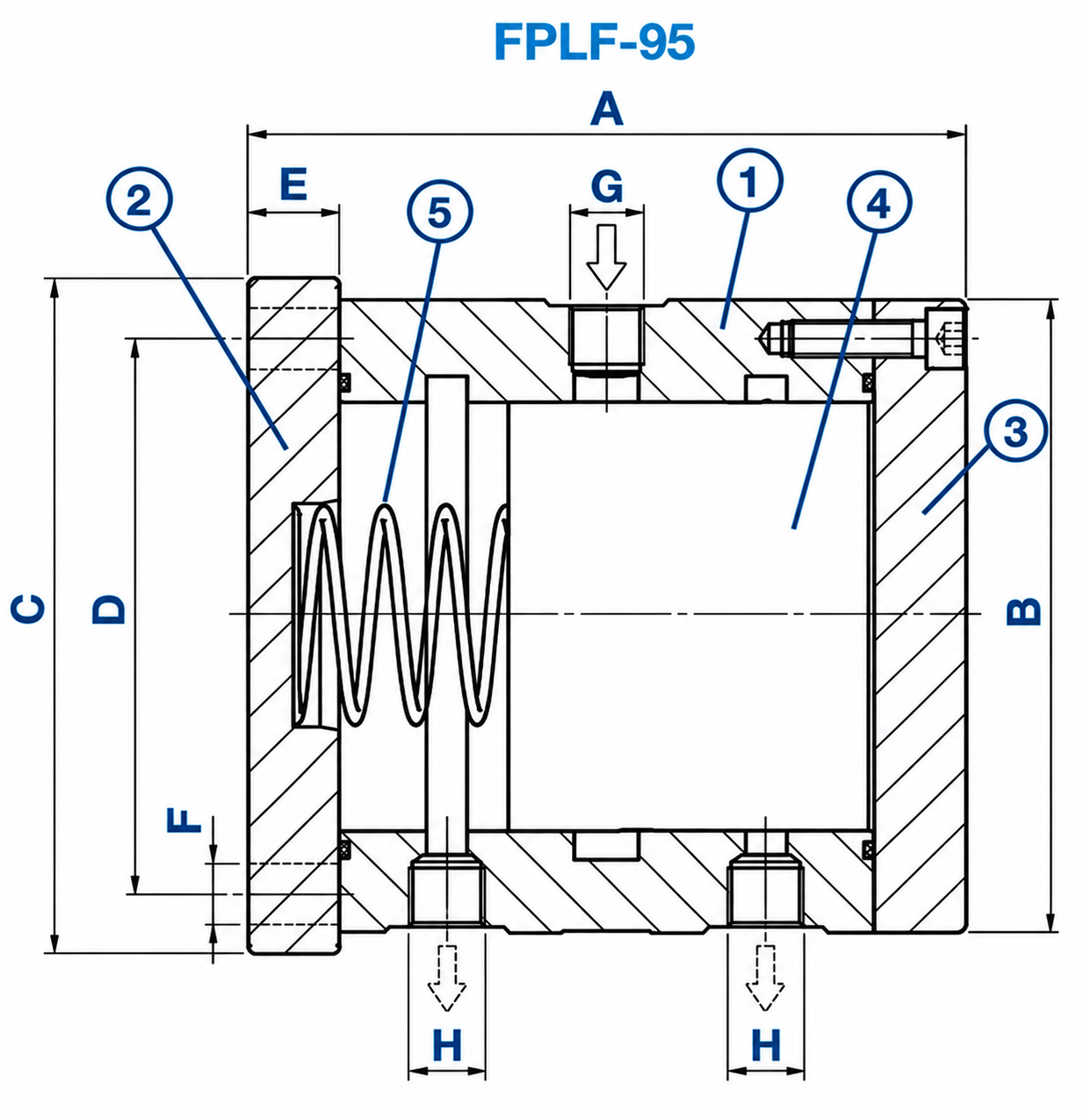
Piston-Vibrators FPLF-50 bis 95
Lubrication-free
pneumatic vibrators for linear vibration with unlimited
fine-tuning facilities for amplitude and frequency.
Properties
- Quiet and efficient
- Lubrification-free
- Rated frequency 1’800 – 2’800 min-1
- Force 490 – 6’150 N
- Continuously variable
- Applicable up to 120°C, HT version up to 150°C
and LT version down to -40°C on request - Resistant against extreme environmental conditions
- Also available with ATEX certification
Field of application
- For foodstuffs and pharmaceuticals,
- Driving conveyor and discharge chutes
- Loosening or compacting of bulk solids
- Activating of mechanical processes
- Filling facilities
Construction
Extra hard and corrosion-resistant surface through aluminium oxide,
generated by titaniferous electrolyte.
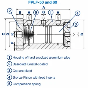
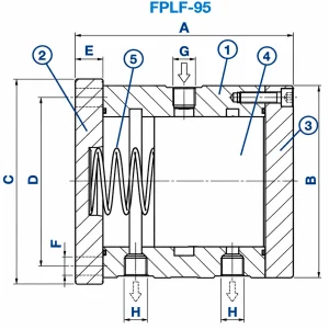
Dimensions and weights
| Model | A [mm] | B [mm] | C [mm] | D [mm] | E [mm] | F [mm] | G Thread | H Thread | J Thread | K | Weight [kg] |
|---|---|---|---|---|---|---|---|---|---|---|---|
| FPLF-50-M | 154 | ø 84 | 90 | 72 | 20 | 8.8 | G 1/4″ | G 1/4″ | G 1/4″ | M16 | 3.05 |
| FPLF-60-M | 154 | ø 94 | 110 | 90 | 20 | 8.8 | G 1/4″ | G 3/8″ | G 1/4″ | M16 | 4.10 |
| FPLF-95-M | 157 | ø 140 | 150 | 125 | 20 | 13.0 | G 3/8″ | G 3/8″ | G 3/8″ | – | 8.75 |
Aluminium housing, coated with hard Ematal
Baseplate hard Ematal coated
Cap anodized
Piston of covered steel
Compression spring
Technical data
| Model | Vibrations [x 1000 min-1] | Force [N] | Air consumption [l/min] | ||||||
|---|---|---|---|---|---|---|---|---|---|
| 2 bar | 4 bar | 6 bar | 2 bar | 4 bar | 6 bar | 2 bar | 4 bar | 6 bar | |
| FPLF-50-M | 1.85 | 2.3 | 2.8 | 490 | 970 | 1’600 | 48.0 | 100 | 190 |
| FPLF-60-M | 1.95 | 2.4 | 2.7 | 610 | 1’400 | 2’170 | 90.0 | 160 | 270 |
| FPLF-95-M | 1.8 | 2.4 | 2.8 | 1’620 | 4’060 | 6’150 | 170.0 | 320 | 450 |
| Weight | N/A |
|---|---|
| Dimensions | N/A |
| SERIES | FPLF-12S ,FPLF-12M ,FPLF-12L ,FPLF-12 XS ,FPLF-18S ,FPLF-18M ,FPLF-18L ,FPLF-25S ,FPLF-25M ,FPLF-25L ,FPLF-35S ,FPLF-35M ,FPLF-35L ,FPLF-50M ,FPLF-60M ,FPLF-95M |
Reviews
There are no reviews yet.