

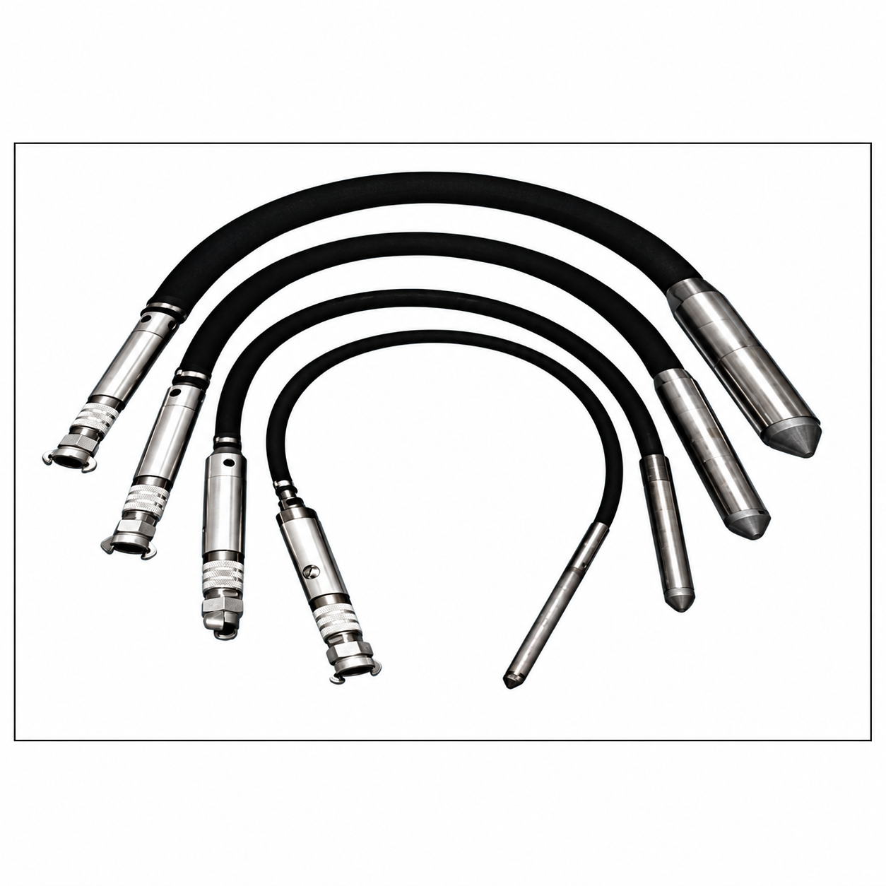
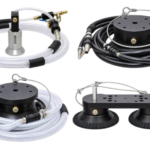
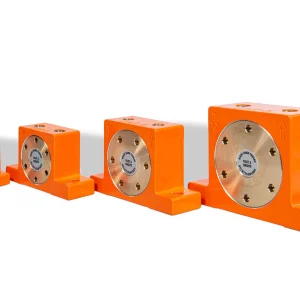
V Series Pneumatic Concrete Poker Vibrator
Price range: $300.00 through $1,300.00


PNEUMATIC INTERNAL VIBRATORS
OPERATING MANUAL

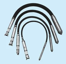
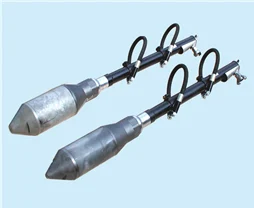
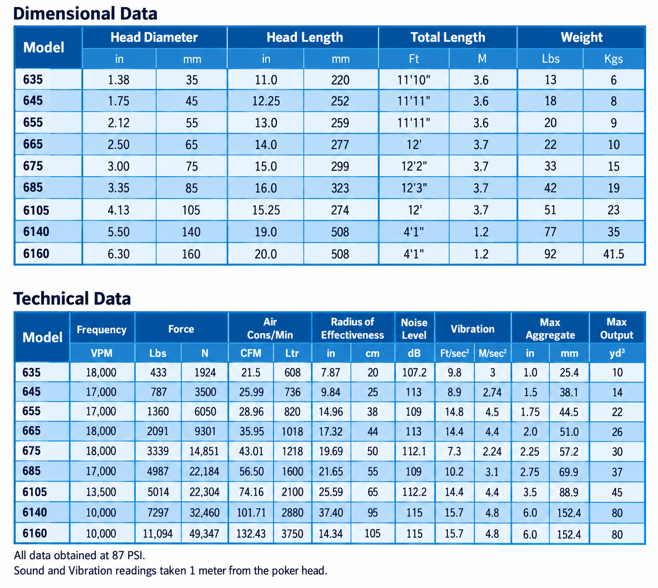
| MODEL | 628 | 635 | 645 | 655 | 665 | 675 | 685 | 6105 | 6140 | 6160 |
|---|---|---|---|---|---|---|---|---|---|---|
| Head Diam. (in) | 1.10 | 1.38 | 1.75 | 2.12 | 2.50 | 3.00 | 3.35 | 4.13 | 5.50 | 6.30 |
| Head Length (in) | 9.21 | 10.9 | 11.2 | 12.4 | 12.9 | 14.4 | 15.5 | 15.5 | 20.0 | 20.0 |
| Frequency (VPM) | 18000 | 18000 | 17000 | 17000 | 18000 | 18000 | 17000 | 13500 | 10000 | 10000 |
| C/F Force (lbf) | 323 | 433 | 787 | 1360 | 2090 | 3338 | 4986 | 5014 | 7297 | 11093 |
| Air Consumption(cfm) | 18 | 21 | 26 | 29 | 36 | 43 | 57 | 74 | 101 | 132 |
| Weight (lbs) | 9.7 | 13 | 18 | 20 | 22 | 33 | 42 | 51 | 77 | 92 |
| Radius of Effectiv. (cm) | 6 | 8 | 10 | 15 | 17 | 20 | 22 | 26 | 37 | 41 |
| S P Level (dB) | 104.5 | 107.2 | 113 | 109 | 113 | 112.1 | 109 | 112.2 | 115 | 115 |
| Vibration (ft/sec²) | 10.5 | 9.8 | 8.9 | 14.8 | 14.4 | 7.3 | 10.2 | 14.4 | 15.7 | 15.7 |
| Air Pressure (psi) | 87 | |||||||||
Air Consumption established with supplied pressure of 87 psi

General Safety
For your personal protection and safety of others around you on site, please read and ensure you fully understand the following safety information.
It is the responsibility of the operator to fully understand how to operate this equipment safely.
If you are not sure consult your supervisor.
Points to remember are:
i.e. Safety goggles, gloves, ear defenders, dust mask and steel toe capped footwear.
Always protect skin from contact with concrete.

Always check the vibrator thoroughly before use for condition and safety.
If any parts are damaged or missing do not use the vibrator until it is repaired or replaced.
To prevent accidental starting of the vibrator, it must be disconnected from the air supply.
Caution must be exercised when touching the vibrator head.
It must be hung up with the head upwards and the control handle open to allow moisture etc. to escape from the vibrator.
The hose should not be held within 1 metre from the head of the vibrator at any time.
Operational exposure time may need limiting if fingers become effected.
OPERATING AND MAINTENANCE INSTRUCTIONS
General Maintenance
Dismantling and Re-assembly Instructions
1. Replacement of Vane and Rotor
Hold housing (4) in a vice and unscrew nosepiece (1A) – right-hand thread.
Remove from the vice and by angling downwards the rotor is free to drop into the hand ensuring not to cause damage.
The parts should be cleaned and examined.
If the nosepiece shows signs of excessive wear, then it should be replaced (see point 4).
Vanes must be a snug sliding fit in the rotor and fitted so that the vane cuts-out face away from the milled slot in the rotor.
Adjust length of vane to 0.004 – 0.006 shorter than the rotor.
Note
Some models (V665-V6105) have nosepieces (1) and separate front closure plates (3).
Dismantling is similar to the above and these two parts are available as spares.
2. Removal of Rear Body, Rear Closure Plate and Hoses
Cut exhaust hose clip (16), pull off exhaust hose (15) from exhaust body (17).
Unscrew exhaust body (17) from lubricator/handle (39/30), then pull out handle to expose hose clip (10).
Cut hose clip (10) to release inlet hose (11) from the handle.
Hold housing (4) in a vice and unscrew rear body (12) – left-hand thread, removing complete with exhaust hose (15).
If the hose is to be replaced then unscrew hose sleeve (13), pull out hose (15) from rear body (12)
and remove hose protection spring (14) – only on models 675 – 6105.
Using inlet hose (11) pull out rear closure plate (7), locking ring (8) and inlet hose connector (9).
All parts should be cleaned and the rear closure plate (7) examined for signs of wear (see point 4).
3. Re-assembly
Rear closure plate (7), inlet hose fitting (9) and inlet hose (11) should be inserted into the housing as an assembly,
ensuring that the plate is kept square to the housing (4) and pushed onto the housing shoulder.
Slide new locking ring (8) over inlet hose (11) and locate behind rear closure plate (7).
If necessary, fix exhaust hose (15) into rear body (12), insert hose protection spring (14) – only models 675 – 6105,
and clamp with hose sleeve (13).
The assembly can then be screwed onto the housing (4) ensuring that a new ‘O’ ring or fibre washer (2) is fitted.
Adjust hose lengths so that the inlet hose (11) protrudes approximately 65mm from the exhaust hose (15).
Slide new clips (10 & 16) onto respective hoses (11 & 15).
Pass inlet hose (11) through exhaust body (17) and fit onto inlet hose connector (18) using hose clip (10).
Screw exhaust body (17) onto control handle (30).
Push exhaust hose (15) onto exhaust body (17) and fit hose clip (16).
4. Wear Criterion
The optimum condition of the vibrator turbine assembly to produce maximum speed and therefore power
is determined by the total air gap of the rotor.
Ideally this should be between 0.002 – 0.005 and a total gap greater than 0.008 greatly impairs the performance.
The length of the rotor is 5.07 – 5.08 when assembled at the factory and if worn below 5.066, it should be replaced.
Models 628, 635, 645, 655, 665, 675, 685 & 6105
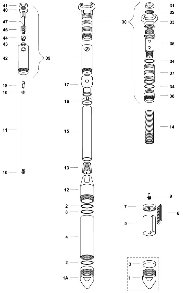
Spare Parts
| Ref. | Description | Qty. | 628 | 635 | 645 | 655 | 665 | 675 | 685 | 6105 |
|---|---|---|---|---|---|---|---|---|---|---|
| 1 | Nosepiece | 1 | – | – | – | – | 16265 | 3551 | 1602 | 16246 |
| 1A | * 1part Nosepiece / FC plate | 1 | 16310 | 16206 | 16216 | 16227 | – | – | – | – |
| 2 | * ‘O’ Ring | 2 | 16314 | 779 | 1808 | 2126 | 16268 | 2330 | 1600 | 16251 |
| 3 | * Front Closure Plate | 1 | – | – | – | – | 16260 | 16230 | 16380 | 16240 |
| 4 | Housing | 1 | 16301 | 16201 | 16211 | 16221 | 16261 | 16231 | 16381 | 16241 |
| 5 | Rotor | 1 | 16302 | 16202 | 16212 | 16222 | 16262 | 16232 | 16382 | 16242 |
| 6 | * Vane | 1 | 16303 | 16203 | 16213 | 16223 | 16263 | 16233 | 16383 | 16243 |
| 7 | * Rear Closure Plate | 1 | 16304 | 16204 | 16214 | 16224 | 16264 | 16234 | 16384 | 16244 |
| 8 | * Locking Ring | 1 | 16307 | 16134 | 7704 | 7663 | 16267 | 7688 | – | 16252 |
| 9 | Inlet Hose Connector | 1 | – | – | 5521 | 16225 | 16225 | 16235 | 16245 | 16245 |
| 10 | Inlet Hose Clip | 2 | 16313 | 137 | 137 | 5456 | 5456 | 5211 | 5211 | 5211 |
| 11 | * Inlet Hose | 1 | 46073 | 788 | 788 | 1583 | 1583 | 540 | 540 | 540 |
| 12 | Rear Body | 1 | 16306 | 2622 | 7701 | 1576 | 16266 | 3553 | 1601 | 16247 |
| 13 | Hose Sleeve | 1 | – | 2623 | 1730 | 1582 | 1582 | 1604 | 1604 | 1604 |
| 14 | Hose Protection Spring | 1 | – | – | – | – | – | 1479 | 1479 | 1479 |
| 15 | Exhaust Hose | 1 | 171 | 2021 | 7985 | 1584 | 1584 | 541 | 541 | 541 |
| 16 | * Exhaust Hose Clip | 1 | Bandit | 3679 | 2392 | 75 | 75 | 76 | 76 | 76 |
| 17 | Exhaust Body | 1 | 16040 | 10225 | 10224 | 10223 | 10223 | 10222 | 10222 | 10222 |
| 18 | Inlet Hose Connector | 1 | 16311 | 10588 | 10588 | 10221 | 10221 | 10219 | 10219 | 10219 |
| 30 | Steel Handle Complete | 1 | 16120 | 16120 | 16120 | 16120 | 16120 | 16120 | 16120 | 16120 |
| 31 | * Rubber Gland | 1 | 81 | 81 | 81 | 81 | 81 | 81 | 81 | 81 |
| 32 | * Gauze Filter | 1 | 156 | 156 | 156 | 156 | 156 | 156 | 156 | 156 |
| 33 | Q / R Coupling | 1 | 2512 | 2512 | 2512 | 2512 | 2512 | 2512 | 2512 | 2512 |
| 34 | * ‘O’ Ring | 2 | 2273 | 2273 | 2273 | 2273 | 2273 | 2273 | 2273 | 2273 |
| 35 | Handle Shaft | 1 | 2261 | 2261 | 2261 | 2261 | 2261 | 2261 | 2261 | 2261 |
| 37 | Twist Grip | 1 | 2260 | 2260 | 2260 | 2260 | 2260 | 2260 | 2260 | 2260 |
| 38 | Adaptor | 1 | 16042 | 16042 | 16042 | 16042 | 16042 | 16042 | 16042 | 16042 |
| 39 | Lubricator Complete | 1 | 10270 | 10270 | 10270 | 10270 | 10270 | 10270 | 10270 | 10270 |
| 40 | Lubricator Tube | 1 | 10289 | 10289 | 10289 | 10289 | 10289 | 10289 | 10289 | 10289 |
| 41 | ‘O’ Ring | 1 | 10273 | 10273 | 10273 | 10273 | 10273 | 10273 | 10273 | 10273 |
| 42 | Lubricator Body | 1 | 10271 | 10271 | 10271 | 10271 | 10271 | 10271 | 10271 | 10271 |
| 43 | ‘O’ Ring | 1 | 2524 | 2524 | 2524 | 2524 | 2524 | 2524 | 2524 | 2524 |
| 44 | Oil Filler Screw | 1 | 2265 | 2265 | 2265 | 2265 | 2265 | 2265 | 2265 | 2265 |
| 46 | Felt | 9 | 2520 | 2520 | 2520 | 2520 | 2520 | 2520 | 2520 | 2520 |
| 47 | Bleed Wire | 1 | 2521 | 2521 | 2521 | 2521 | 2521 | 2521 | 2521 | 2521 |
| Opt. | Rubber Nosepieces | 1 | – | 16208 | 16218 | 16229 | 19145 | 3611 | – | – |
OPERATING AND MAINTENANCE INSTRUCTIONS
General Maintenance
Dismantling and Re-assembly Instructions
1. Replacement of Vane and Rotor
Hold housing (3) in a vice and unscrew nosepiece (1) – right-hand thread.
Remove front plate (7) using 16mm extractor.
This allows the rotor (5) and vane (4) to be removed for inspection for wear and damage.
Vanes must be a snug sliding fit in the rotor and fitted so that the vane cuts-out face away from the milled slot in the rotor.
Adjust length of vane to 0.1 – 0.15mm shorter than the rotor.
2. Removal of Rear Body
Undo nut (36) and remove handle (35), then undo nut (24) and clamp nut (21).
You can then unscrew rear body (6) – left hand thread.
Should the rear plate (8) need to be removed, this can be pressed out.
You will need to remove the rotor first from the vibrator to do this.
Re-assembly is opposite to the above, but in order to refit the clamp nut (21),
you will need to use M12 female extractor to slightly stretch the inlet hose (17)
to line up the thread with the hole in the tube.
Once the clamp nut has been fitted, the rest of the handle can be assembled.
3. Removal of Bushing
Hold handle tube (34) in a vice and unscrew nut (10) – right-hand thread.
Unscrew locking nut (13) – left hand thread, the tube will now separate from the rubber bushing (14).
To fit a new bushing(14), replace the locking nut (13) and push new bushing into place.
Place tube with the new bushing into the rear body(6) and refit nut(10).
4. Wear Criterion
The optimum condition of the vibrator turbine assembly to produce maximum speed and therefore power
is determined by the total air gap of the rotor.
Ideally this should be between 0.002 – 0.005 and a total gap greater than 0.008 greatly impairs the performance.
The length of the rotor is 4.33 when assembled at the factory and if worn below 4.32, it should be replaced.
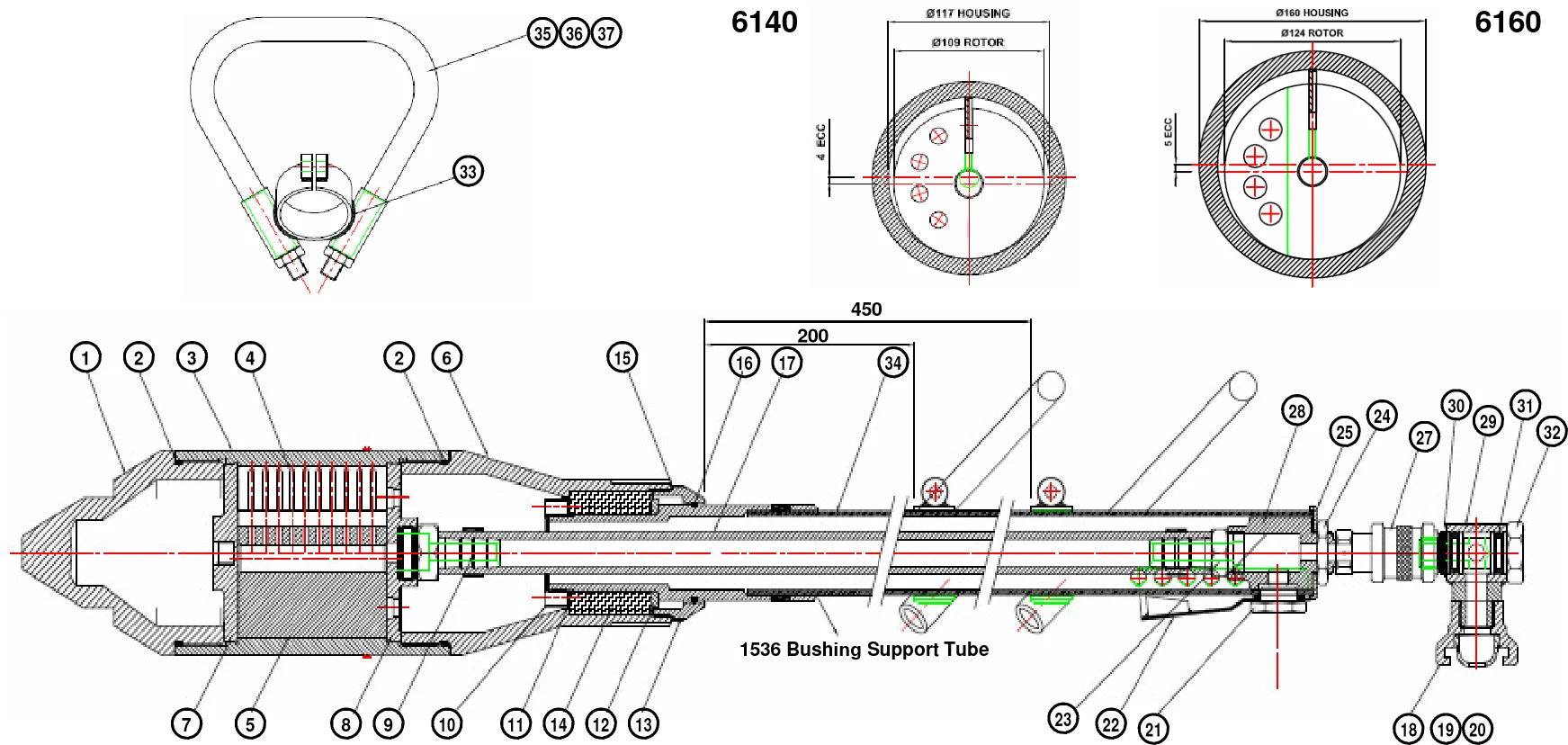
Spare Parts
| Ref. | Description | Qty. | V6140 | V6160 | Ref. | Description | Qty. | V6140 | V6160 |
|---|---|---|---|---|---|---|---|---|---|
| 1 | * Nose piece | 1 | 7500 | 16393 | 24 | Lock Nut | 1 | 1564 | 1564 |
| 2 | ‘O’ Ring | 2 | 1534 | 16395 | 25 | Cover | 1 | 16430 | 16430 |
| 3 | Housing | 1 | 7501 | 16388 | 27 | Slide Valve | 1 | 46155 | 46155 |
| 4 | Vane | 1 | 16353 | 16394 | 28 | Rear Inlet Body | 1 | 16432 | 16432 |
| 5 | Rotor | 1 | 7503 | 16389 | 29 | Exhaust Banjo Fitting Assy | 1 | 16429 | 16429 |
| 6 | Rear Body | 1 | 1533 | 16390 | Exhaust Banjo Sleeve | 1 | 16433 | 16433 | |
| 7 | * Front Closure Plate | 1 | 7502 | 16392 | Exhaust Banjo Inlet | 1 | 16434 | 16434 | |
| 8 | * Rear Closure Plate | 1 | 7504 | 16391 | 30 | External Circlip | 1 | 16180 | 16180 |
| 9 | Inlet Hose Connector | 1 | 1528 | 1528 | 31 | ‘O’ Ring | 2 | 16181 | 16181 |
| 10 | Nut (bush support tube) | 1 | 1539 | 1539 | 32 | Banjo Spindle | 1 | 16431 | 16431 |
| 11 | Front Spacer | 1 | 1542 | 1542 | 33 | Handle Clamp Assy | 2 | 16355 | 16355 |
| 12 | Rear Spacer | 1 | 1544 | 1544 | Tube (flexible handle) | 2 | 1555 | 1555 | |
| 13 | Nut (rear body) | 1 | 1538 | 1538 | Clamp Collar | 2 | 16367 | 16367 | |
| 14 | Bushing(shock absorbing) | 1 | 1540 | 1540 | Hex Head Screw | 2 | 16373 | 16373 | |
| 15 | Sealing Ring Rear | 1 | 1541 | 1541 | Hex Nyloc Nut | 2 | 16374 | 16374 | |
| 16 | ‘O’ Ring | 1 | 2330 | 2330 | M8 Plain Washer | 2 | 46017 | 46017 | |
| 17 | * Inlet Hose | 1 | 2021 | 2021 | 34 | Support Tube Assy | 1 | 16363 | 16363 |
| 18 | Quick Release Joint | 1 | 1654 | 1654 | Bushing Support Tube | 1 | 1536 | 1536 | |
| 19 | * Rubber Gland | 1 | 81 | 81 | Rigid Exhaust Tube | 1 | 16364 | 16364 | |
| 20 | * Gauze Filter | 1 | 156 | 156 | 35 | Flexible Handle Assy | 2 | 1657 | 1657 |
| 21 | Exhaust Shield Clamp Nut | 1 | 16428 | 16428 | Flexible Handle Connector | 2 | 1556 | 1556 | |
| 22 | Exhaust Deflector | 1 | 1646 | 1646 | 36 | Hex Nyloc Nut Thin Type | 4 | 1559 | 1559 |
| 23 | Hose Fitting | 1 | 1636 | 1636 | 37 | M14 Plain Washer | 4 | 16372 | 16372 |
9921-K Tanner Rd.
Houston, TX 77041
800-320-4044 | +713-939-0404 Phone
866-630-0404 | +713-939-7213 Fax
www.HoustonVibrator.com
sales@houstonvibrator.com
| Weight | N/A |
|---|---|
| SERIES | V628 ,V635 ,V645 ,V655 ,V665 ,V675 ,V685 ,V6105 ,V6140 ,V6160 |
Reviews
There are no reviews yet.